Most people can do simple decimal addition in their heads, and even advanced addition using common rules like carrying. Here’s how we’d add 6 + 7:
  1
   6
+  7
----
  13
Adding 6+7 gives a result of 3, with a 1 as a carry. In the final step, the 1 carry simply falls down as a 10 on the result, giving 10 + 3 = 13 as the final result.
It may seem extensive to go through this for such a simple operation, but it’s quite important to know of the carry method when we go on.
Binary addition
Just as we added two decimal numbers, we can do the exact same in binary. In binary 6 is represented as 0b110 while 7 is represented as 0b111. Take a look:
First we add the first (rightmost) column, resulting in a 0b1 in the sum:
   110
+  111
------
     1
Next up we add the second column. In this case the two ones produce the result 0b10 – meaning we’ll get a sum of 0b0 and a carry of 0b1:
   110
+  111
------
    01
Then we add the third column. Ignoring the carry, 0b1 + 0b1 gives a sum of 0b10. Adding the 0b1 we had in carry, we get 0b11 – resulting in a sum of 0b1 as well as a carry of 0b1:
  11
   110
+  111
------
   101
And finally we add the final column, in this case containing nothing but the carry:
  11
   110
+  111
------
  1101
And there we go – 0b1101 = 13 = 6 + 7.
Implementing a simple ALU that does addition
Now that we can do binary addition by hand, lets recreate a very simple arithmetic logic unit that’ll do the same. The ALU is at the very core of the CPU that’s powering your machine right now. It’s the hearth that does all of the arithmetic and logical operations that are required to run the computer.
In the following I will generally talk of single bits as being enabled/positive/true/1 or being disabled/negative/false/0. All four designations mean the same and will be used depending on the context.
The half adder
The first step is to implement what’s known as a half adder#Half_adder). This is the circuit that takes two bits and adds them together. The result is a sum value as well as a carry. Both can be either 0 or 1.
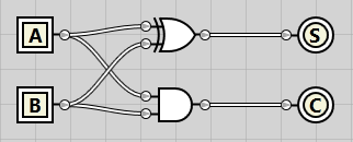
In the following circuit we get two inputs from the left, bits A and B. Both A and B are connected to an XOR gate. The XOR gate (top) gives an output of 1 iff (if and only if) only one of the inputs have a value of 1. If A and B have the same value, it gives a result of 0. This is just what we need for the sum – remember, 0b1 + 0b1 gave a result of 0b10 – a sum of 1 and a carry of 0. The XOR gate is thus used to calculate the sum – denoted S in the circuit below.
Both A and B are connected to an AND gate as well (bottom). The AND gate gives a result of 1 iff both A and B are 1, in all other cases it gives a result of 0. This is just what we need – if both A and B are 1, it means we get an output of 1 – the carry.
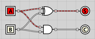
If we enable A, we see how the signal propagates through the XOR gate and results in an enabled sum:
The result is exactly the same if we just enable B instead:

And finally, if we enable both, we get a disabled sum but an enabled carry instead:

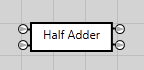
As we’ll be reusing the half adder in the next circuit, I’ve converted it into an integrated circuit (IC). On the left we have the input bits A and B on top & bottom respectively. On the right we have the sum on top and the carry at the bottom.
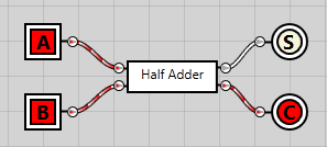
Having created the half adder IC, we can now simplify our circuit somewhat:
The full adder
At this point we have a fully working ALU capable of adding two 1-bit numbers and outputting a 2-bit result. As most computers today are either 32-bit or 64-bit, we obviously need to expand our ALU’s capabilities. Let’s work towards making it accept two 2-bit inputs instead.
To do so we first need to create another component, the full adder#Full_adder). While the half adder is great for working with just two inputs, to calculate the next column we need to take three inputs – bits A and B, as well as the potential carry C. The result, as before, should still be a sum as well as a carry.
Technically what we’re creating is called a 1-bit full adder, since it’s able to add two 1-bit numbers while also respecting the carry input.
In the following circuit we use two of the half adder IC’s that we created before. Bits A and B are hooked into the first one, while the carry bit is hooked into the second half adder. The sum from the first half adder is used as the second input to the second half adder.
The end sum is a direct sum from both the half adders. For the sum to be enabled, both half adders must produce an enabled sum. Both carry outputs are connected to an OR gate. As the name implies, the OR gate will output a positive result if either of the inputs are enabled.
If we enabled the A bit, the sum passes right through both half adders and results in a positive sum output:

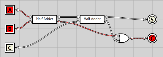
If we enabled both A and B, the first half adder gives a carry output, which passes right through the OR gate and results in a positive carry output:
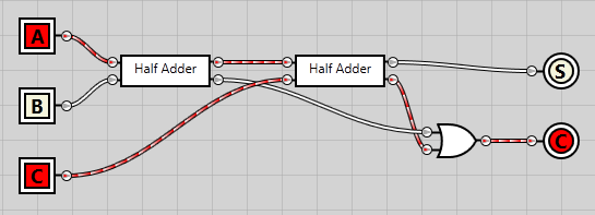
And finally, if we enable the input carry bit as well, we get a carry output from the first half adder and a sum output from the second one:

The way the circuit is constructed, it doesn’t matter which of the bits are enabled, only the amount of them. If one is enabled, we get a positive sum. Two enabled results in a positive carry. And finally, if all three are enabled, we get a positive sum as well as a positive carry.
Just to demonstrate, we can disable the B input and get the same positive carry result as we got with the A and B bits enabled:
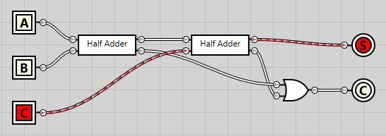
Just as we can disabled all but the carry input and get a sum output, just like when only the A bit was enabled:
Having created this circuit, we can now convert it into a full adder IC and simplify our diagram:
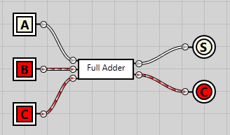
Chaining 1-bit full adders to create a 3-bit ripple carry adder
Now that we’re able to easily add two 1-bit numbers using our full adder, let’s try and chain them up so we can add two 2-bit numbers.
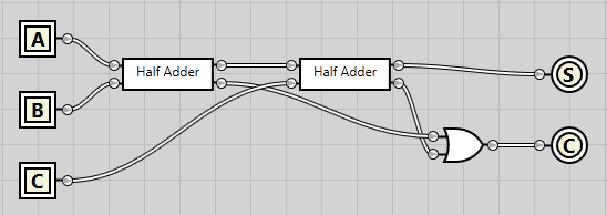
In the following diagram we have two 2-bit inputs. The first output bit of both inputs are connected to the A and B inputs on the first full adder (rightmost one). Likewise, the second output bits from each input is connected to the A and B inputs on the second full adder. The carry output from the first full adder is connected to the carry input on the second full adder.
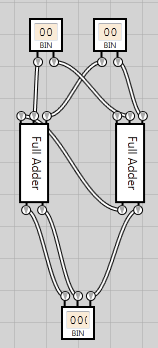
Now, we started out wanting to add the numbers 6 and 7. To do so, we need a 3-bit adder so we can express the input numbers 6 and 7, both requiring three input bits.
At this point it’s a trivial operation to extend the adder with one more bit. We simply connect each output bit from the first input to the A bits on each full adder. Likewise we connect each output bit on the second input to the B input bits on each full adder. The carry from the first full adder is added as carry input to the second, and likewise for the second and third full adders.
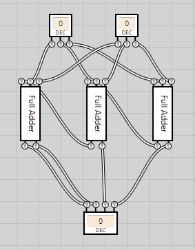
By using the decimal inputs we can now type the input numbers 6 and 7 and see our whole circuit in action, providing the correct output of 13:

And there we go, we’ve now created a 3-bit ripple carry adder#Ripple_carry_adder).
Conclusion
I’m sure (read: hope) I’m not the only one having the nightmare of an apocalyptic event occurring here on Earth. Imagine the scenario, you’ve got all of the materials in the world as well as all the manpower you need. Unfortunately, you’re the only computer scientist that’s survived. Given time, manpower and materials, would you be able to rebuild the computer as we know it today?
Each layer you peel off of the computer arms you with more knowledge and capability, not just at that layer, but at all of the layers that lie above. Knowing about gate logic enables you to understand so much more of how the CPU works as well as what’s actually being performed once you write “int x = 6+7;” in your application (assuming you also know about all of the layers between the logic gates and your C#/other high level code).
Naturally there are more layers to peel. For instance, you could create your own XOR/AND/OR gates using the base NAND gate. And you could create your own NAND gates using nothing but interconnected transistors. And you could create your own transistors using… You get the point.
I can’t help but feel in total awe of the amount of technology that’s packed in each and every CPU that’s shipped to a home computer somewhere. Experimenting with electrical circuits is lots of fun, and you learn loads from it.
If you want to try it out for yourself, go grab a copy of Steve Kollmansbergers (free) open source Logic Gate Simulator.