So what’s a multiplexer you ask? A multiplexer is an integrated circuit that takes a number of inputs and outputs a smaller number of outputs. In this case we’re aiming at creating a 4-to-1 multiplexer. As the name implies, it takes four inputs and outputs exactly one output, determined by a select input. Depending on the number of input lines, one or more select lines may be required. For 2n input lines, n select lines are needed. In hardware terms, this is basically the simplest of switches.
Creating a 2-to-1 multiplexer
To start out easy, we’ll create a multiplexer taking two inputs and a single selector line. With inputs A and B and select line S, if S is 0, the A input will be the output Z. If S is 1, the B will be the output Z.
The boolean formula for the 2-to-1 multiplexer looks like this:
Z = (A ∧ ¬S) ∨ (B ∧ S)
If you’re not used to boolean algebra, it may be easier to see it represented in SQL:
SELECT @Z = (A & ~S) | (B & S)
By ANDing A and B with NOT S and S respectively, we’re guaranteed that either A or B will be output. Creating the circuit, it looks like this:
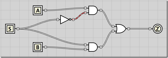
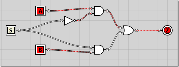
If we enable both A and B inputs but keep S disabled, we see that the A input is passed all the way through to the Z output:
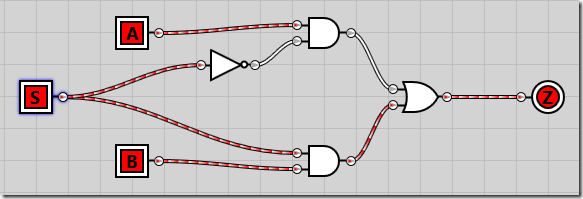
And if we enable the S selector line, B is passed through to Z as the output:
Creating a 4-to-1 multiplexer
Now that we’ve created the simplest of multiplexers, let’s get on with the 4-to-1 multiplexer. Given that we have 22 inputs, we need two selector lines. The logic is just as before – combining the two selector lines, we have four different combinations. Each combination will ensure that one of the input lines A-D are passed through as the output Z. The formula looks like this:
Z = (A ∧ ¬S0 ∧ ¬S1) ∨ (B ∧ S0 ∧ ¬S1) ∨ (C ∧ ¬S0 ∧ S1) ∨ (D ∧ S0 ∧ S1)
And in SQL:
SELECT Z = (A & ~S0 & ~S1) | (B & S0 & ~S1) | (C & ~S0 & S1) | (D & S0 & S1)
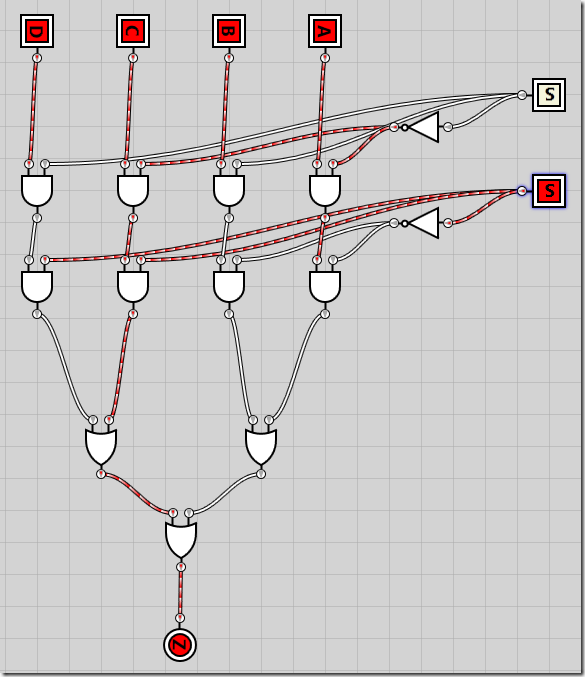
The circuit is pretty much the same as in the 2-to-1 multiplexer, except we add all four inputs and implement the 4-input boolean formula, with S0 on top and S1 on bottom:
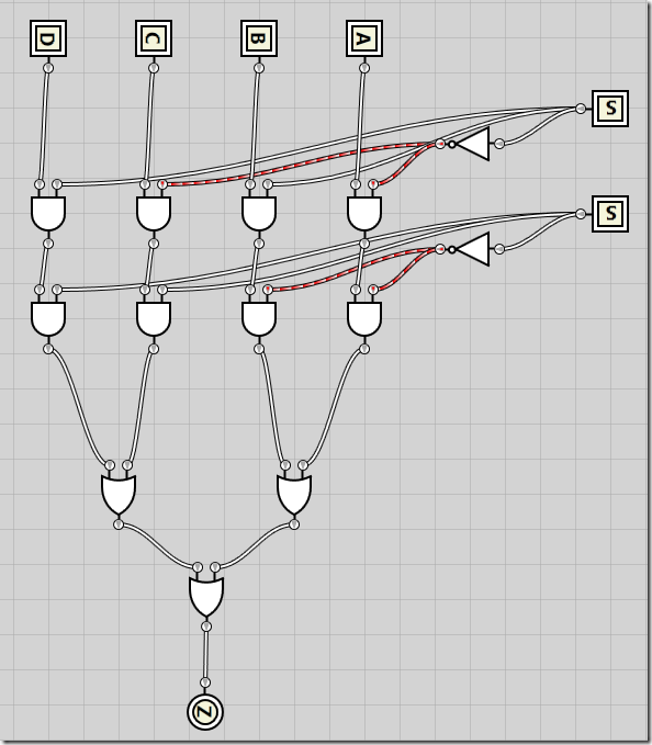
I’ll spare you a demo of all the states and just show all four inputs activated while the signal value of 0b10 results in C being pass through to Z as the result:
Combining two 4-to-1 multiplexers into an 8-to-1 multiplexer
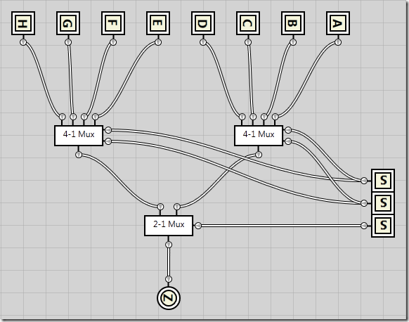
I’ll spare you the algebraic logic this time as it follows the same pattern as previously, except it’s starting to become quite verbose. In the following circuit I’ve taken the the exact 4-to-1 multiplexer circuit that we created just before, and turned it into an integrated circuit (just as I converted the 2-to-1 multiplexer into an integrated circuit). I’ve then added 8 inputs, A through H as well as three selector inputs, S0 through S2.
S0 and S1 are passed directly into each of the 4-1 multiplexers, no matter the value of S2. This means both 4-1 multiplexers are completely unaware of S2s existence. However, as the output from each of the 4-1 multiplexers are passed into a 2-1 multiplexer connected to the S2 selector line, S2 determines which of the 4-1 multiplexers get to deliver the output.
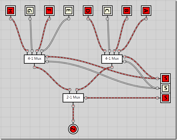
Here’s an example where S2 defines the output should come from the second (leftmost) 4-1 multiplexer, while the S0 and S1 selector lines defines the input should come from the second input in that multiplexer, meaning input F gets passed through as the result Z.
Combining two 8-to-1 multiplexers into a 16-to-1 multiplexer
Ok, let’s just stop here.Using the smaller multiplexers we can continue combining them until we reach the desired size.